.svg)
How to edit AI-generated structural design using intuitive tools and structural analysis as helpers
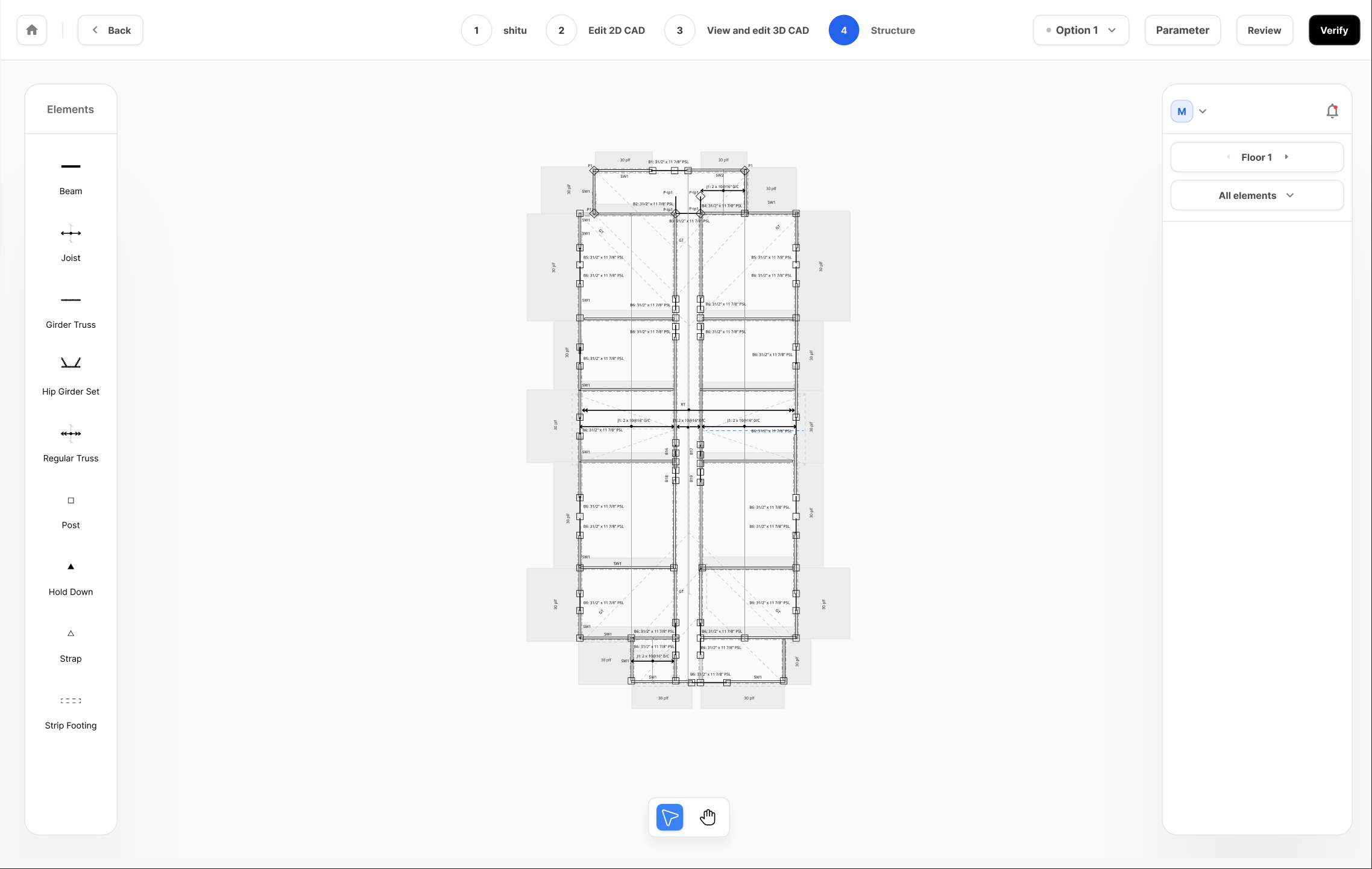
After you select a design option, you'll enter the Structural Editor, the primary environment for refining your project. The editor is designed to give you complete control over every structural element.
The main part of your screen is the Canvas, where your structural plan is displayed in a 2D view. On your structural plan, you will be able to view not only the key architectural and structural elements based on your previous steps of architectural modeling and the AI-suggested layout, as well as critical loading-passing locations (both points and linear distribution) with visualizations of how large the loads are. This information helps you better assess the current design by understanding the force demand from related structures above the current level. You can flip through floor levels through the navigation button on the left.
On the left side of the screen, you'll find the Toolbar, which contains tools for adding new structural elements to your design, such as beams, joists, posts, and foundation components.
When you select an element on the canvas, a Properties Panel will appear on the right. This is a context-sensitive menu where you can make detailed adjustments. Here, you can modify the element's Material Selection, changing its size, grade, and type. The panel also displays a Detailed Analysis summary, showing key performance data like the element's Demand-Capacity Ratio (DCR) and deflection, which update each time you re-run the analysis.
The Structural Editor provides a consistent set of actions for manipulating all structural components. Mastering these fundamental operations will allow you to quickly and efficiently refine your design.
To add a new element, simply select the corresponding tool from the Toolbar (e.g., Beam, Post, etc.) and drop it directly onto the canvas.
To delete an element, first select it with a single click on the canvas, then press the delete key on your keyboard or use the context menu.
You can move any selected element by clicking and dragging it to a new position; the snapping tools will help you place it precisely.
You can also reshape most elements. For linear components like beams and walls, you can change their length by clicking and dragging their endpoints. If you press the Shift key on your keyboard, you can change the length of the element without changing its direction. For area-based elements like joist zones or strip footings, you can adjust their boundaries by clicking and dragging the vertices that define their polygonal shape. There will be snapping to align with existing elements to help make your actions more precise.

A crucial feature of the Structural Editor is the ability to see detailed analysis results for every component. When you select a structural element, the Properties Panel displays key performance metrics from the most recently completed simulation. Understanding these numbers is essential for validating and optimizing your design.
The most important metric is the DCR (Demand-Capacity Ratio). This value, expressed as a percentage, tells you how much of an element's structural capacity is being used by the loads applied to it. A DCR of 90%, for example, means the element is at 90% of its limit. A DCR over 100% indicates the element is overstressed and has failed the check. Depending on the element type and the forces it resists, you will see different types of DCR, such as Moment DCR for bending and Shear DCR for shear forces.
For bending members like beams and joists, you will also see Deflection results. This is typically shown with the calculated deflection distance and the corresponding percentage of the allowable limit (e.g., 0.5" (90%)). This allows you to quickly see if the element meets the serviceability requirements you defined during project setup.
If you click on the detailed analysis button, you'll access the detailed structural modeling of each component and its key structural performance. The exact information displayed varies by the type of structural components, but overall you should be able to gain further insights on how gravity and lateral forces have an impact on this particular component.

It's important to remember that these results are a snapshot of the last successful analysis. If you make any changes to the structural model, these numbers will no longer be current, and you will need to re-run the analysis to see the impact of your edits.
In the Structural Editor, you have full control over the framing layout. You can select any beam or joist to move, delete, or modify it. To change an element's size or material, select it and use the Properties Panel. For beams, you can configure the number of plies, width, depth, and material (e.g., Parallam, Microllam, Timber, steel). For joists, you can choose from standard lumber (configuring width, depth, material, and spacing), engineered timber products like TJI (configuring depth, grade, and spacing), or steel.
Adding new elements is just as simple. Select the beam or joist tool from the toolbar on the left-hand side and drop it on the plan. The editor's snapping tools will help you precisely align the new element with existing walls, posts, and other beams, ensuring an accurate layout.

Vertical support elements are also fully editable. You can add, move, or delete posts anywhere on your plan. When a post is selected, the Properties Panel allows you to choose from a list of predefined post types or define a custom post by specifying its material, ply, and dimensions.
Walls are categorized as bearing or non-bearing, and you can toggle this property for most walls. A key feature is the ability to convert a standard bearing wall into a Shear Wall and in the opposite direction. When you designate a wall as a shear wall, you unlock additional options in the Properties Panel to define its specific configuration, including the sheathing type, thickness, and nailing pattern. This allows you to build a detailed and accurate lateral system directly within the editor.
For roof framing, the editor provides tools for working with both Girder Trusses and Regular Trusses. You can add these elements to build out your roof's structural system. The drawing tools are equipped with snapping functionality, which helps you align the trusses perfectly with the architectural roof lines, walls, and other framing members you've already defined. You can also move, delete, or resize trusses as needed to complete your roof design.
Detailed connections are a critical part of the structural plan, and you can manage them directly in Genia. You can add Hold-downs and Straps to your design from the toolbar. These connection elements are designed to snap to walls and posts.
Typically, you will add a hold-down or strap by selecting the post or wall where it is needed. In the Properties Panel for that element, you can then select the specific model and type for the connection from a dropdown list. This direct association ensures that the connection is properly integrated with the supporting member and will be accurately reflected in the final drawings and calculations.
To help you work quickly and accurately, the Structural Editor features an intelligent snapping system. As you draw, move, or resize elements, they will automatically "snap" to key geometric points on the canvas. This includes the endpoints and centerlines of walls and beams, the intersections of grid lines, and the center of posts. This ensures that your framing is perfectly aligned without the need for manual measurement.
Additionally, you can hold down the Shift key while drawing to lock the tool to horizontal, vertical, or 45-degree angles, making it easy to create a clean and orderly layout.