.svg)
This section documents how the editor models and verifies gravity (vertical) load paths for low- to mid-rise residential and light-commercial buildings. It covers load definition, tributary-area distribution, load combinations in accordance with U.S. model codes and referenced standards.
The workflow begins by defining loads by case. Dead load is taken as 15 psf by default, or as specified by the user. Live loads are assigned by occupancy, with a default value of 40 psf per IBC 2021, or as specified by the user. Roof snow and roof live loads are obtained from the ASCE load tool. Once load cases are defined, the editor assembles ASD and LRFD combinations in accordance with ASCE 7, and also maintains a serviceability set (e.g., D, D+L, D+Lr/S).
For sloped roofs, roof live and snow loads are first applied to the surface area and collected by the trusses or joists. Based on the spacing of each joist, tributary areas are defined between adjacent members, and the corresponding uniform line loads are applied to each joist. The reactions from all joists or trusses are then idealized into tributary areas that transfer loads to supporting beams and bearing walls. These beams receive concentrated point loads at their connection points and transfer them to posts or columns.

Vertically, reactions are aggregated story by story, primarily through bearing walls and posts. The vertical loads from the upper floor are carried down and supported by the beams or bearing walls of the story below. Where vertical elements such as posts or walls are offset between levels, an allowance of up to 2 ft is permitted to be considered aligned. If the offset exceeds 2 ft, our model assigns additional supporting members at the lower level to transfer the load properly. At the base, foundation elements receive the accumulated axial and shear demands, which are then checked for allowable bearing and overall stability using either presumptive values permitted by the IBC or project-specific geotechnical parameters.
Two-Story Timber Frame: Gravity Load Path & Checks
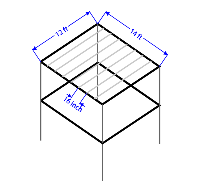
Joist span: $L_j = 12\text{ft$ (simple span), spacing $s = 16\text{in} = 1.333\text{ft}$
Center beam span (per floor):
$L_b = 14\text{ft$ (simple span)
Two floors (Level 2 over Level 1), posts stack to a spread footing
Floor dead load:
$q_D = 15\text{psf}$
Floor live load:
$q_L = 40\text{psf}$
Presumptive allowable soil bearing: $q_{\text{allow}} = 1{,}500~\text{psf}$
Material (illustrative): floor joists $2\times 10~\text{DF No.2}$
$b=1.5~\text{in},~h=9.25~\text{in},~E=1.6\times 10^6~\text{psi},~M=1765~\text{ft}\cdot\text{lb},~V=1665~\text{lb}$
Beam material (illustrative for deflection check): ${PSL}~~2.0E~~3~1/2\times 9~1/2$
$b=3.5~\text{in},~h=9.5~\text{in},~E=2.0\times 10^6~\text{psi},~M=13055~\text{ft}\cdot\text{lb}, ~V=6430~\text{lb}$
Serviceability limits (floors): $\Delta_L \le L/360$$, $$\Delta_T \le L/240$
Post material : $4\times 4~\text{DF No.2}$
$N=4917~lb$
Service (deflection): use $D$, $L$, and $D+$
Strength (ASD example): $D+L$
Dead: $w_{D,j} \;=\; q_D \cdot s\;=\; 15~\text{psf} \times 1.333~\text{ft}\;=\; \boxed{20.0~\text{plf}}$
Live: $w_{L,j} \;=\; q_L \cdot s\;=\; 40~\text{psf} \times 1.333~\text{ft}\;=\; \boxed{53.33~\text{plf}}$
Total: $w_{T,j} \;=\; w_{D,j} + w_{L,j}\;=\; 20.0 + 53.33\;=\; \boxed{73.33~\text{plf}}$
Maximum moment (uniform load): $M_{\max} \;=\; \frac{w\,L_j^2}{8}\;=\; \frac{73.33~\text{plf}\times (12~\text{ft})^2}{8}\;=\; \boxed{1{,}320~\text{ft}\cdot\text{lb}}$
Maximum shear: $V_{\max} \;=\; \frac{w\,L_j}{2}\;=\; \frac{73.33~\text{plf}\times 12~\text{ft}}{2}\;=\; \boxed{440~\text{lb}}$
Section properties($2\times 10$$actual): $$I \;=\; \frac{b\,h^3}{12}\;=\; \frac{1.5\times 9.25^3}{12}\;=\; \boxed{98.93~\text{in}^4}$
Use $L=12~\text{ft}=144~\text{in$$ and convert line load to $$\text{lb/in}$$: $$w^\ast=w/12$.
Live-load deflection:
$\Delta_L \;=\; \frac{5\,w_L^\ast\,L^4}{384\,E\,I}, \quadw_L^\ast=\frac{53.33}{12}=4.444~\text{lb/in}$
$\Delta_L \;=\; \frac{5(4.444)(144^4)}{384(1.2\times 10^6)(98.93)}\;=\; \boxed{0.210~\text{in}}\;\le\; L/360=144/360=0.400~\text{in}$
Total deflection:
$\Delta_T \;=\; \frac{5\,w_T^\ast\,L^4}{384\,E\,I}, \quadw_T^\ast=\frac{73.33}{12}=6.111~\text{lb/in}$
$\Delta_T \;=\; \frac{5(6.111)(144^4)}{384(1.2\times 10^6)(98.93)}\;=\; \boxed{0.288~\text{in}}\;\le\; L/240=144/240=0.600~\text{in}$
Result (joist serviceability): OK.
Total equivalent line load: $w_{b,T} \;=\; \,q_T\,L_j\;=\; (15+40)\times 6\;=\; \boxed{330~\text{plf}}$
Live-only line load: $w_{b,L} \;=\; \,q_L\,L_j\;=\; 40\times 6\;=\; \boxed{240~\text{plf}}$
Maximum moment (service total): $M_{\max} \;=\; \frac{w_b\,L_b^2}{8}\;=\; \frac{330\times 14^2}{8}\;=\; \boxed{8085~\text{ft}\cdot\text{lb}}$
Maximum shear (service total): $V_{\max} \;=\; \frac{w_b\,L_b}{2}\;=\; \frac{330\times 14}{2}\;=\; \boxed{2310~\text{lb}}$
Section properties(${PSL}~~2.0E~~3~1/2\times 9~1/2$)
$I \;=\; \frac{b\,h^3}{12}\;=\; \frac{3.5\times 9.5^3}{12}\;=\; \boxed{250.07~\text{in}^4}$
Use $L=14~\text{ft}=168~\text{in}$$ and convert line load to $$\text{lb/in}$$: $$w_{}^\ast=w_{}/12$.
Live-load deflection:
$\Delta_L \;=\; \frac{5\,w_{b,L}^\ast\,L^4}{384\,E\,I}, \quadw_{b,L}^\ast=\frac{240}{12}=20~\text{lb/in}$
$\Delta_L \;=\; \frac{5(20)(168^4)}{384(2.0\times 10^6)(250.07)}\;=\; \boxed{0.415~\text{in}}\;\le\; L/360=168/360=0.467~\text{in}$
Total deflection:
$\Delta_T \;=\; \frac{5\,w_{b,T}^\ast\,L^4}{384\,E\,I}, \quadw_{b,T}^\ast=\frac{360}{12}=30~\text{lb/in}$
$\Delta_T \;=\; \frac{5(30)(168^4)}{384(2.0\times 10^6)(250.07)}\;=\; \boxed{0.622~\text{in}}\;\le\; L/240=168/240=0.700~\text{in}$
Result (beam serviceability): OK.
Per-floor beam end reaction: $(4\times 4~\text{DF No.2})$
$R_{b,\text{serv}} \;=\; \frac{w_{b,T}\,L_b}{2}\;=\; \frac{330\times 14}{2}\;=\; \boxed{2310~\text{lb}}$
Two stacked floors on a line post (neglecting self-weight here):
$P_{\text{serv}} \;=\; 2310 + 2310\;=\; \boxed{4620~\text{lb}}\le\; N=4917~lb$
Result (post serviceability): OK.
Required footing area: $A_{\text{req}} \;=\; \frac{P_{\text{serv}}}{q_{\text{allow}}}\;=\; \frac{4620~\text{lb}}{1{,}500~\text{psf}}\;=\; \boxed{3.08~\text{ft}^2}$